
VARIABLE BYPASS REACTORS IN THE NEW 500 kV TRANSMISSION SYSTEM Operation of electrical networks The operation of electrical systems is subject to fluctuations in the consumption of electrical energy; Likewise, the incorporation of wind and solar renewable energy contributes to the variability of the operating conditions of the transmission network during the day and at […]
VARIABLE BYPASS REACTORS IN THE NEW 500 kV TRANSMISSION SYSTEM
Operation of electrical networks
The operation of electrical systems is subject to fluctuations in the consumption of electrical energy; Likewise, the incorporation of wind and solar renewable energy contributes to the variability of the operating conditions of the transmission network during the day and at night, weekdays and weekends.
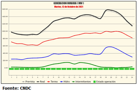
Real-time generation must permanently adjust to these variations. The figure shows the generation curve of the SIN (National Interconnected System) which varies from 978.4 MW (01:00 hrs) to 1588.0 MW (19:30 hrs). Variations in electricity generation produce an imbalance in reactive power in the electricity transmission system, accompanied by changes in the voltage level.
The continuous growth of the consumption of electrical energy at the national level, has promoted the need to expand the electrical transmission system to a higher voltage level until now existing. This new voltage level of 500 kV, unprecedented in the Bolivian electricity grid, poses new challenges in the stages of development of studies, engineering, construction, commissioning and, later, in the commercial operation and maintenance of said facilities.
The challenge in the operation of electrical networks
The challenges in the operation of electrical networks at a global level, has motivated us to innovate in new equipment that contributes to voltage regulation. In order to provide reactive power flexibly, Variable Shunt Reactors (VSRs) are the preferred solution. VSRs combine conventional iron core reactors with the addition of tap changers that have been used in high voltage transformers for many years. With their regulating unit, VSRs provide variable reactive power and allow rapid adaptation of the grid voltage
The expansion of the electricity transmission system in the SIN
ENDE Transmisión as transmitting agent of the Wholesale Electricity Market (MEM) is executing the project “Transmission Line in 500 kV Santiváñez – Carrasco”. As part of the scope of the electrical installations of the project, inductive reactive power compensation reactors are installed linked to the transmission line through switches. The reactors have a nominal power of 35 MVAr at a voltage of 500 / √3 kV. At each end of the Santiváñez – Carrasco 500 kV transmission line, a bank of 3×35 MVAr single-phase reactors plus a reserve unit has been designed in order to control the voltages produced by the “Ferranti Effect”. Likewise, as supplementary voltage control elements in the transmission network, variable reactors with a total bank power of 63 to 105 MVAr are installed in the busbar system of the Santiváñez and Carrasco substations, composed of three 21+ single-phase units 17×0.824 MVAr. In the one-line diagram below you can see the location of the VSRs in the substations.
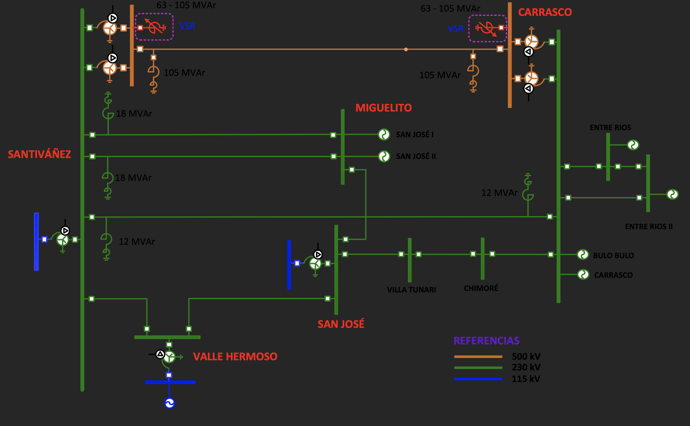
One-line diagram of the 500 kV network with variable reactors (VSR)
Diseño y modo de operación del VSR
Shunt variable reactors are designed with air-gapped iron core. The iron core conducts and concentrates the magnetic flux that needs to close the air gaps. The images show the photographs of the General Electric brand variable reactors that are installed in the busbar system of the 500 kV Santiváñez and Carrasco substations.
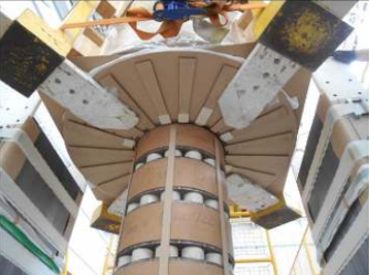
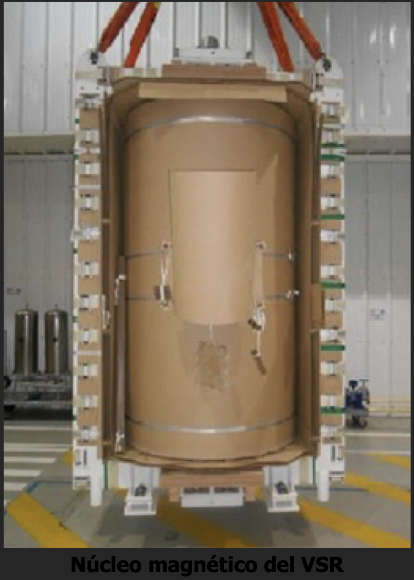
The difference in the permeability of electric steel and oil (oil permeability is equal to air or vacuum) is very large, it is enough to work with the magnetic resistance of air gaps. They reduce inductivity and increase the performance of this arrangement (figure left).
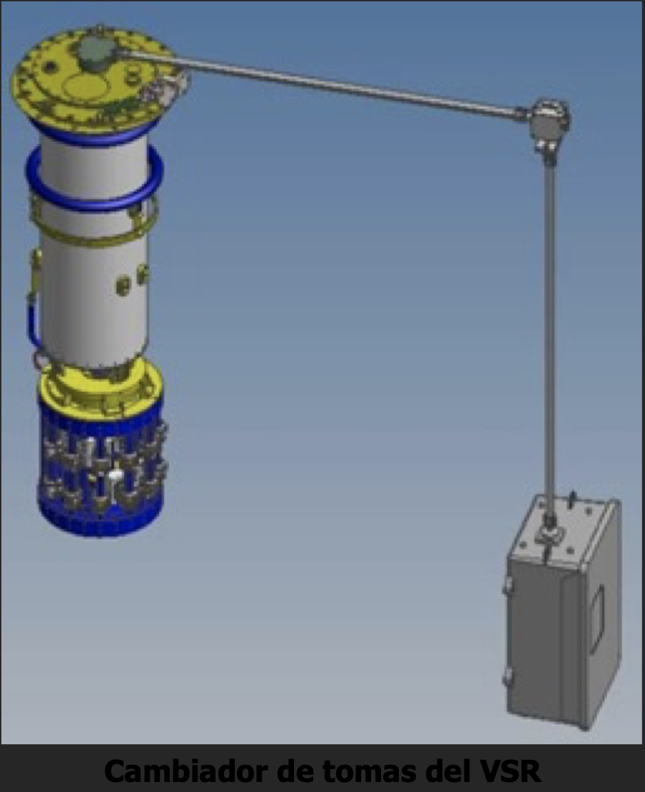
The VSR operating principle is based on the change of the number of turns in the winding. Therefore, the windings are equipped with tap changers, which connect and disconnect turns. Tap changers have been used for many years in power transformers for voltage regulation (right figure).
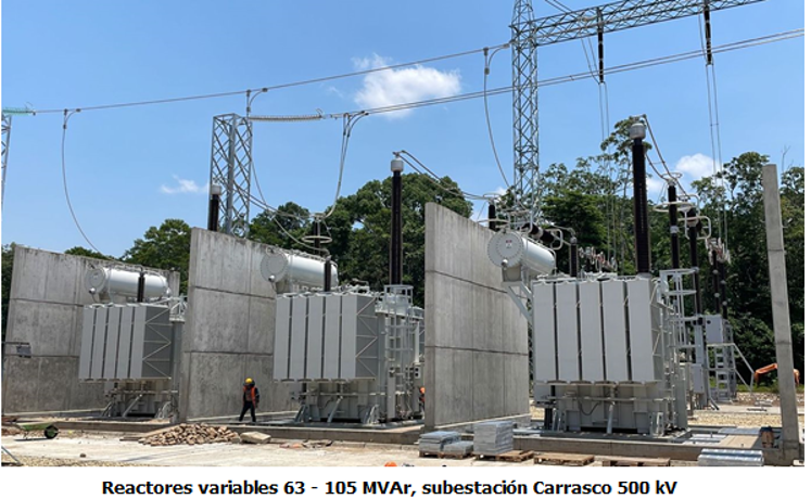
In the figure below you can see in a panoramic photograph the variable reactors of the Carrasco 500 kV substation.
Performance of the VSR in the electrical network of the SIN
The analysis of the operation of the VSR in the SIN electrical network has been carried out with DIgSILENT’s PowerFactory software, in which all the components of the transmission, generation and distribution system are modeled.
In the analysis, two events have been considered that demonstrate how the VSRs contribute substantially to the voltage control of the 500 kV system: 1) Disconnection of the 105 MVAr line reactor of the Santiváñez substation and 2) Increase in the load in the form of a ramp.
-
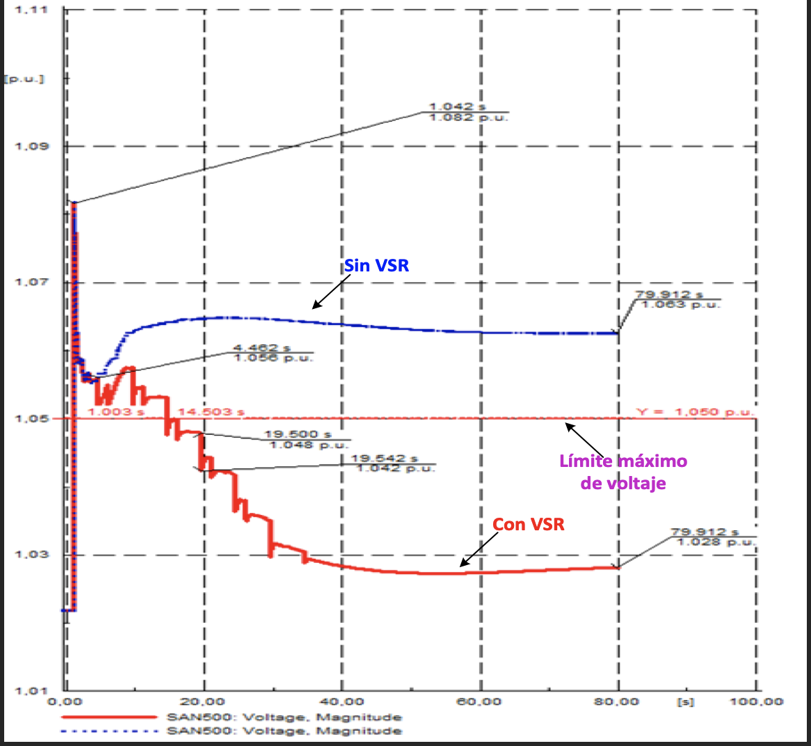
Disconnection of line reactors (105 MVAr) Santiváñez end
The figure shows in blue the voltage level reached without considering the VSR (fixed reactor) and in red the voltage level with the action of the VSR tap changer, the horizontal line in red represents the maximum voltage limit acceptable in normal operation 1.05 pu (525 kV).
As can be seen, the blue line is above the maximum voltage limit with 1,063 pu (542 kV), on the contrary, with the actuation of the tap changer the voltage is reduced to a value of 1,028 pu (514 kV).
-
Rampa de carga de 50 % en 50 seg
In this case, the demand in the Eastern zone increases by 50% in 50 seconds, which means an increase from 242 MW to 325 MW. The figure shows the voltage response in Santiváñez 500 kV busbars without the actuation of the variable reactors (blue) and with the actuation of the tap changers of the variable reactors (red). Finally, when the voltage seems to settle at a value at which the variable reactors of Carrasco and Brechas have reached the operating limit of their tap changers (0.984 pu); the order of disconnection of a bar reactor (63 MVAr) is given to obtain a voltage with a higher value.