
-
January 6, 2022
Isolation coordination
Atmospheric surges
The present article of review of the Norma IEC 60071-1 and IEC 60071-2, aims to be a tool for determining tensions supported of coordination of overvoltages Front fast using the method Simplified described in Annex F of the normative
It is important to mention that the estimation of the ray current or the amplitude wave’s front will be subject to a wide range of variables as a ceramic level of the geographical place in the which is located the project, resistivity of the Land, Return Periods, Polarity Positive or negative lightning, among others.
In turn, aspects such as the level Ceráunico are variable statistics dependent on the precision of the monitoring plants environmental and a good Management of the data history.
Therefore, the norm raises a method Simplified for the estimation of the overvoltages due to lightning, which in general terms assumes that the Line entry bays and the main electrical equipment of the substation will be protected by surge and lightning dischargers, properly selected low The IEC 60099-4 standard.
Before performing the calculation of the amplitude of the representative voltage of the beam Some hypotheses should be assumed as it should be:
- The wave front slope is cushioned mainly by the Crown effect of the lines of transmission, it is worth saying that for rays far from the substation Amplitude of the wave will be less.
- Investment primed do not occur in the tower closest to the substation due to proximity of the grounding of the substation.
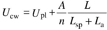
Therefore, the norm raises the expression F.17:
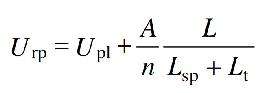
Where;
(URP) Amplitude of the representative voltage of the ray (KV).
(A) Lightning behavior factor Depending on the type of transmission line.
(UPL) Level of protection of the type wave Lightning Ray (KV).
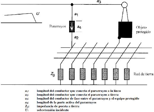
(L) Distance of separation from the lightning rod and the equipment to be protected (M).
(n) Minimum number of lines connected to the substation (n = 1 or n = 2).
(Lsp) Length of the average vain (M).
(Lt) Portion of the airline that has A rate of defects equal to the rate of established return (M).
(Rt) Return rate of overvoltage, Established (1 / year).
(Rkm) Annual defects rate of the corresponding transmission line to the first kilometer of line from of the substation, (1/100 km / year).
Incorporating the expression F.18 It has:
Obtaining the supported tension of Coordination for the ray impulse:
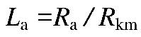
La Portion of the airline whose rate Default is equal to the Acceptable Established failure rate.
Ra Acceptable fault rate of equipment.
Factor A for different types of lines
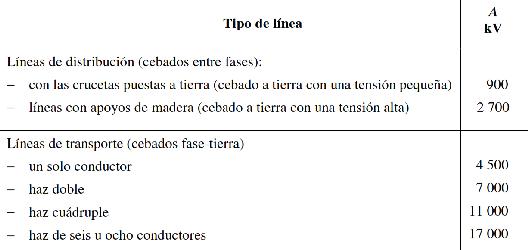
For electrical equipment the rate of Acceptable failure RA due to overvoltages are in the range of 0.001 / year up to 0.004 / year.For electric transmission lines Acceptable fault rates due to rays are in the range of 0.1 / 100 km / year Up to 20/100 km / year.
In Bolivia it is a common practice assign for lines at 115 kV and 230 kV, two (2) Net departures 100 km / year and for lines at 500 kV, one (1) Net departure 100 Km / year.
It is important to indicate that the protection characteristics of a lightning rod are only valid in its location, in that sense, the greater the separation distance between the lightning rod and The protected team, the lower the effectiveness protector for this team and could Exceed the level of protection of the lightning rod.
Below is the elements that must be taken into account to determine the distance of separation From the resort to the protected equipment (L).
It is pertinent to make a comparison of the calculation of the protection distance of a lightning lights made by the simplified method with respect to the method of Simulation with software.
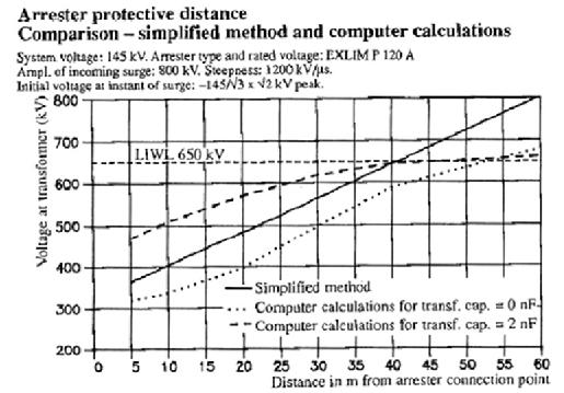
According to the graph, with the method Simplified more values are obtained conservatives, being able to overcome the bearable tension for atmospheric discharge at 40 meters from Distance from the resort to the protected equipment.
However, the simulation method By software usually requires introducing parameters such as amplitude of the current of the atmospheric discharge that will be subject to studies Middle environmental statisticians or reports of similar characteristics projects.It is common to find amplitudes atmospheric discharge current of the order of 150 kA, 200 kA and 250 kA, However, the choice of one or the other value will depend on the information available for each project and finally of the proper selection of the engineer Electric design, since each parameter will offer different results.
Also, the behavior of the front of wave once it is entered the Substation will depend on aspects such as the contact state of the Power switches (open / open Closed), the capacitance of electrical equipment, the type of conductors Electric bar and grounding of the substation among others.
Below you can see the Wave behavior Atmospheric when the switch is in an open position:
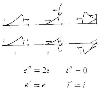
As can be seen for the curve of tension there is a reflection of the wave by having a discontinuity that produces an overlap and elevation tensile.
On the other hand, the electrical equipment of the substation will also play an important role regarding attenuation Wave front as can be seen below:
Effect of tension transformer Capacitive and lightning rod in an electrical substation
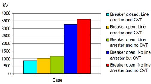
In the graph you have the results of The voltage measured in the power switch for a wave amplitude of 2000 kV, as can be observed lowest level of overvoltage happens In the case of closed switch, Bay line with lightning and transformer capacitive stress, as long as, Situation more criticism happens with open switch and line bay without lightning or transformers of capacitive tension.
Capacitive voltage transformers have a capacitance between 4-8 NF and the power transformers of 2-4 nf.
Finally, it is important to indicate that for the range I (1 kv & lt; um≤ 245 kV) Standard supported tensions include short-term supported voltage at frequency Industrial and tension supported at ray impulse, therefore, the proper selection by the designer of the supported tensions and Normalized for the ray impulse They will grant reliability to electrical installations by guaranteeing electrical distances phase-earth and phase-phase Internal and external isolation.
Raúl Salamanca Cossio. Gerencia de Planificación.IEC 60071 Partes 1 y 2, IEC 60099. ABB High Voltage Surge Arrester.Download the original document at the following link Descargar -
December 31, 2021
-
-
October 21, 2021
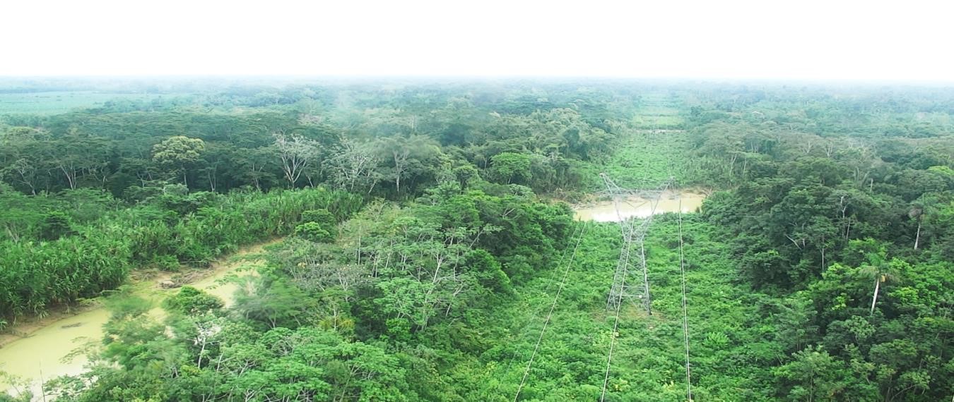
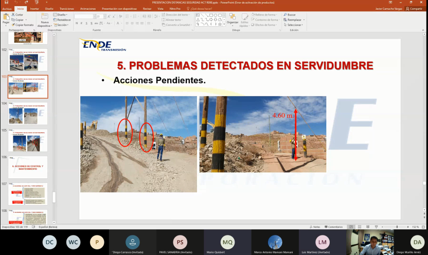
RIGHT OF WAY AND ELECTRICAL SAFETY DISTANCES ON HIGH VOLTAGE POWER LINES
331 / 5000 Translation results Safety distances and rights of way are included in what is called “SERVIDUMBRE”. The easement of power lines is the right granted by the Plurinational State of Bolivia to the licensee to build and install transmission lines and access them for their control and maintenance.
Each line has a particular right of way, established by an express resolution of the regulatory body, in this case the Bolivian Electricity and Nuclear Technology Authority (AETN).
In that sense, as established by the Bolivian Electricity and Nuclear Technology Authority through Resolution AE 409/2019, it details the following:
“By virtue of said easements, the owners and users of the servant estates, cannot carry out works, constructions or works of any nature within the Security Belt (Right of Way), which disturb, damage or endanger the transport service of electricity in the country. Unless it is at your own risk, as long as they respect the minimum safety distances to the electrical conductors of the transmission lines and other restrictions that are regulated in resolution AE 409/2019, which is mandatory ”.
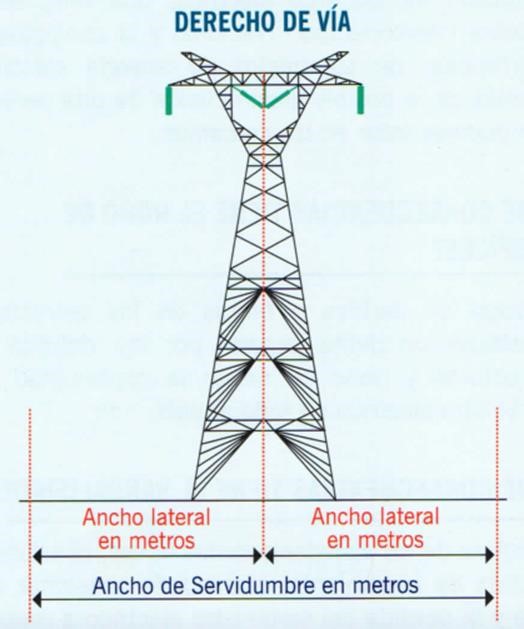
Right of way: Also called a security strip, it is an area defined along the entire line and delimited by a horizontal distance distributed in equal parts from the axis of the line to both ends. This is calculated based on factors considering the possible buckling of the conductor by wind, the technical characteristics of the line, the topography and the vegetation cover.
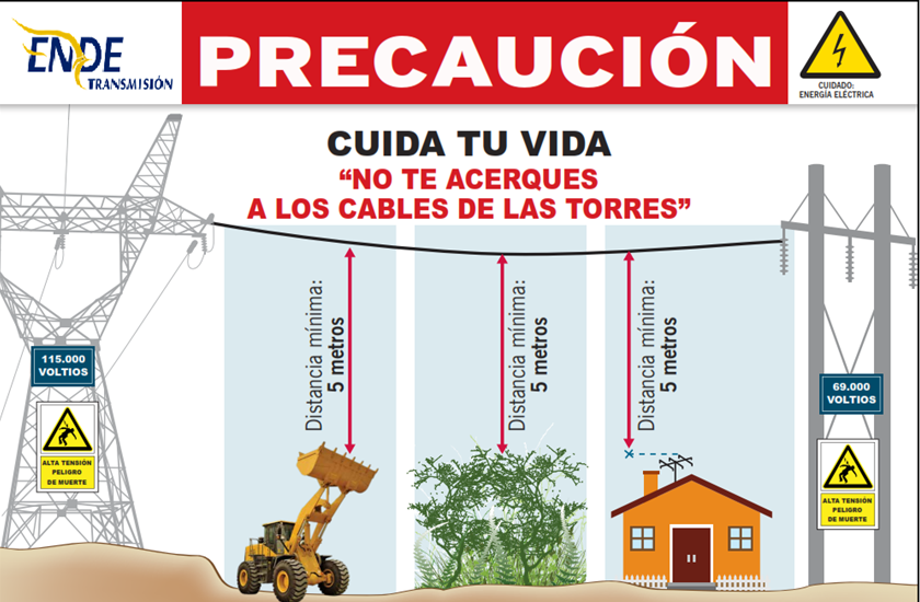
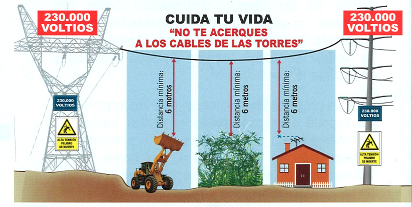
In the case of these transmission lines, the width of the right-of-way (or security strip) depends on the voltage level, as can be seen below:
NOMINAL VOLTAGE 69 kV 115kV 230kV 500kV 23-31 (m) 31 (m) 38 – 61 (m) 61 – 92 (m) Safety Distances: Safety distances are the minimum distances that must be maintained in the air between energized parts (conductors) and physical elements in their immediate vicinity (roads, buildings, houses, trees, land, etc.) in order to avoid accidental contacts and thus guaranteeing the safety of people. The safety distances are vertical and horizontal, which are established in Resolution AE No. 409/2019.
MAIN ENDE TRANSMISIÓN’S ACTIVITIES:
ENDE TRANSMISIÓN S.A. In compliance with Resolution AE 409/2019, it carries out preventive and corrective maintenance activities on high voltage lines in order to prevent personal accidents and guarantee the safety of the population.
The maintenance activities carried out include line inspections, measurements of horizontal and vertical distances in case of detecting any irregularity, the repair of conductors or another component of the line, cutting of dangerous vegetation and the construction of variants.
Line inspections are carried out in order to detect buildings, roads, constructions or vegetation that may represent a risk of contact with energized parts of the line and that may represent a substantial risk to the population.
Within the operational controls within the Right of Way, the following can be highlighted:
- Prohibition of the use of explosives, in which it is controlled that third parties do not carry out blasting
- Prohibition of burning of any type of material, in which it is verified during inspections that third parties do not burn of any kind.
- Prohibition of construction of buildings that exceed the safety distances established in Resolution AE N ° 409/2019.
- Prohibition of operational activities of third parties that do not respect the safety distances within the right of way and established in Resolution AE No. 409/2019
- Control of the growth of tall species vegetation, to prevent accidental contact with an energized component of the line.
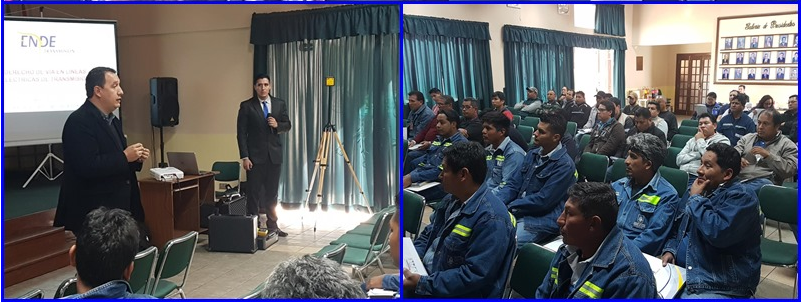
Also, under a criterion of prevention of accidents that may arise in one or more fatalities, through the Occupational Health and Safety area, the workshop on “SAFETY IN CONSTRUCTIONS WITH PROXIMITY TO ENERGIZED HIGH VOLTAGE ELECTRICAL LINES” has been developed, in which the dissemination of the Right of Way and Safety Distances was made to different Municipal Governments and companies in the telecommunications sector, in order to create a close bond with third parties and public order institutions, so that controls are more efficient and thus restrict the authorizations of irregular constructions and the expansion of urban areas within the right of way of high voltage lines.

-
June 10, 2021